How to Choose a PoE Switch for Security Cameras: Ports, Power Budget and Uplinks
.sl-poe table{border-collapse:collapse;width:100%;margin:22px 0}.sl-poe th,.sl-poe td{border:1px solid #bdcbd0;padding:12px;text-align:left;vertical-align:top}.sl-poe th{background:#edf4f2}.sl-poe .table-scroll{overflow-x:auto}.sl-poe figure{max-width:760px;margin:28px auto}.sl-poe img{max-width:100%;height:auto;display:block;margin:auto}.sl-poe figcaption{font-size:14px;line-height:1.6;color:#425c63;padding-top:9px}
An eight-port PoE switch is not automatically an eight-camera system. One port may be needed for the network connection, the total power supply may be smaller than eight times the per-port limit, and a high-power camera may require a standard the switch does not support. Counting sockets is only the beginning.
Choose a camera switch by its usable powered ports, per-port capability, shared power budget and the traffic crossing its uplink. Then check cooling, management and the installation environment. This guide shows the calculations with explicitly hypothetical camera loads, so you can replace them with the figures for your own equipment.
Start with the recorder layout
Decide whether you need a separate switch at all. A compatible NVR with sufficient built-in PoE ports may already supply the cameras. A separate switch can be useful for a camera group in another part of the building, independent camera access or a recorder without integrated power ports.
Draw where the camera streams go. If the recorder and cameras connect to the same switch, most recording traffic can stay there. If their only path crosses an uplink, that link must carry the combined streams. The PoE installation guide explains the whole-system decision before you choose a particular switch.
Count every connection
Write down cameras, recorder, router, downstream switches and any other network devices using the box. An ordinary port used as an uplink is no longer available for a camera. Some products provide dedicated uplink ports; others do not.
Eight camera ports plus two uplinks is different from eight total ports. The product title may not make that distinction obvious, so inspect the interface table and photographs. Avoid buying a smaller unit and assuming a passive cable splitter will create another independent camera connection.
| Connection | Illustrative ports needed | Power requirement |
|---|---|---|
| Six cameras | 6 | Compatible PoE on each |
| Router uplink | 1 | Usually data only for this connection |
| Recorder on the same switch | 1 | Normally separately powered; check the device |
| Spare capacity | At least one additional desired connection | Count its power as well as its socket |
In this example, an eight-port box is full before future expansion. You could choose a different topology, but that should be a deliberate design change rather than a discovery after unboxing.
Match the PoE standard to each camera
Look for the exact IEEE requirement in the camera documentation. Marketing terms such as PoE, PoE+ and PoE++ are useful shorthand, but the standard, type and supported power level are the specifications that need to match.
The commonly encountered 802.3af arrangement provides up to 15.4 W at the source, with up to 12.95 W available for the powered device under its defined conditions. For 802.3at Type 2, the corresponding figures are 30 W and 25.5 W. The difference accounts for power lost along the supported cabling arrangement; it is not spare power you can allocate to another camera.
Huawei’s PoE reference distinguishes source and device figures. Higher-power equipment needs its own documented compatibility check. Do not assume that a port marked 30 W will satisfy a camera requiring a higher type merely because the camera draws less during a brief idle test.
Typical consumption is not your only budgeting number
A camera may use little power while standing still in a warm room with its lights off. Its infrared, spotlight, heater or motor can change that load. Check the maximum consumption and the power class or allocation the switch actually reserves.
Some management interfaces display measured consumption while the source still reserves a larger amount for the device. Others support negotiated or configured allocation. Use the switch’s documented budgeting method, not whichever number produces the cheapest shopping list.
Axis’s power-consumption paper explains why maximum load matters when designing a system. If the specification gives power at the camera, also account appropriately for the source-side requirement and cable losses. Do not add the same allowance twice when you are already using a source-side class allocation.
A worked six-camera power budget
Assume, purely for illustration, four cameras each require a 15.4 W source allocation and two require 30 W each. This is not a specification for every fixed or PTZ camera. The arithmetic describes a proposed inventory whose requirements have already been checked.
| Devices | Source allocation per device | Total |
|---|---|---|
| Four lower-power cameras | 15.4 W | 61.6 W |
| Two higher-power cameras | 30 W | 60 W |
| Required combined allocation | — | 121.6 W |
A source with a 120 W shared budget would be insufficient for that allocation even if it has six ports labeled 30 W. A 153 W budget leaves 31.4 W in this example, before checking environmental restrictions, other devices and the available ports. That is not permission to assume every listed watt remains available under every installation condition.
Reserve enough capacity for the additions you actually expect. One future high-power camera may need more than a generic percentage allowance. Document both the planned load and the proposed expansion instead of applying a round-number margin without understanding the result.
A real datasheet example: read the version, not just the name
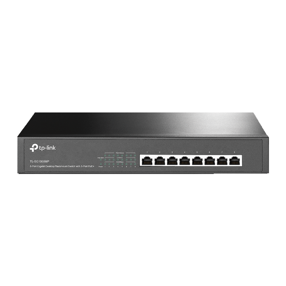
The TP-Link product page consulted for this guide lists eight Gigabit PoE+ ports, up to 30 W per port and a 153 W total budget. Eight times 30 W is 240 W, which is plainly not the stated shared budget. This is a practical example of why the two limits must be checked separately.
The same page lists a fan and an operating-temperature range. Hardware revisions and regional availability can differ, so match the purchased revision with its own documentation. This example illustrates how to read a specification, not a claim that it is the best switch for every home.
Work out what crosses the uplink
Suppose eight cameras each transmit an 8 Mbps recording stream through one uplink. That is 64 Mbps of video before considering additional streams, protocol overhead and playback or management traffic. A 100 Mbps connection may leave less practical margin than its headline speed suggests.
A Gigabit uplink can provide useful headroom without requiring every camera to have a Gigabit port. Many camera streams are much smaller than a port’s maximum link speed. Increasing link speed does not automatically improve the lens, image quality or configured bitrate.
Use actual configured stream rates, and consider additional viewers or multiple recording destinations. Our data and storage calculator helps with stream arithmetic, but storage estimates are not a complete switch-performance test.
Managed versus unmanaged switches
An unmanaged switch can suit a small, straightforward installation with compatible equipment and no need for advanced controls. A managed model can make port status, power allocation, errors and configuration more visible, which may be valuable when diagnosing several cameras.
Management also creates responsibility. Record configuration changes, protect administrator access and keep the device supported. VLANs and port isolation can be useful when correctly designed, but an incorrect rule can prevent cameras from reaching the recorder.
Do not choose a managed model solely to collect feature names. Choose it when someone can configure and maintain the functions the installation needs. TP-Link’s switch-selection guide is one primary reference for comparing those operational choices.
Useful features with tradeoffs
Power schedules can intentionally turn ports off; they can also explain an apparently mysterious recurring outage. Automatic recovery may reboot an unresponsive device, but repeated restarts should not conceal failing cable or insufficient power. Preserve logs and find the cause.
Long-distance modes may reduce link speed and change the supported connection conditions. They are not a free upgrade to every port. Check the exact switches and cameras involved before enabling one across an installation.
For exposed cameras, review surge protection and the manufacturer’s cabling requirements separately from the switch’s packet-handling features. A lightning-related marketing label is not a substitute for a properly installed protective arrangement.
Noise, heat and mounting are purchase decisions
A fan-equipped switch may be suitable in an equipment cupboard and irritating beside a bed. A fanless unit still needs the stated ventilation and temperature conditions. Do not hide either in an airtight container because the appearance is inconvenient.
Allow accessible space for cable bends, labeling and servicing. A larger box with tidy ports and a documented power budget can be easier to maintain than several adapters occupying a power strip. Include the installation location when comparing prices.
Backup-power sizing should include the switch’s own consumption and the equipment it supplies without double-counting the same load. Add the recorder and relevant network devices as appropriate. See the camera UPS guide for that system-level question.
Check the unit when it arrives
Confirm the model, revision, supplied power equipment and port markings before installing it. Record the configuration, then connect devices incrementally while checking status. A short bench test provides a baseline before long cables and outdoor connectors are introduced.
Test normal night-mode operation and other expected high-load functions using approved controls. Review the recording timeline, not only port lights. If one camera disappears when several others activate illumination, examine allocation and physical connections rather than immediately blaming the app.
Your buying worksheet
| Write down | Why it belongs in the quotation |
|---|---|
| Exact camera list and PoE requirements | Prevents a standard or per-port mismatch |
| Required source allocation | Establishes the shared budget |
| All physical connections | Includes uplinks, recorder and expansion |
| Traffic paths and expected streams | Identifies the busiest link |
| Management and service owner | Ensures the chosen controls will be maintained |
| Location and power backup | Includes noise, heat, safe installation and outages |
Compare suppliers on the same worksheet. The cheapest price is not comparable if one quote includes the appropriate power supply and usable uplink while another silently omits them.
Frequently asked questions
Can an eight-port PoE switch power eight cameras?
Only when the required connections and power fit. Check whether an uplink uses one of those ports and whether the shared budget supports all cameras.
Does a 30 W port force 30 W into a camera?
Standards-compliant active PoE negotiates an appropriate supported arrangement; the port rating is a capability limit. Passive or proprietary equipment must not be assumed equivalent.
Will a bigger switch improve picture quality?
Not directly. It can remove a power or network constraint, but optics, lighting, exposure and recording settings determine the image.
For the broader installation and existing buying comparisons, use the camera directory. Select the switch after defining the system it must support.