How to Install PoE Security Cameras: Plan the Wiring, Power and Recording Before Drilling
.sl-poe table{border-collapse:collapse;width:100%;margin:22px 0}.sl-poe th,.sl-poe td{border:1px solid #bdcbd0;padding:12px;text-align:left;vertical-align:top}.sl-poe th{background:#edf4f2}.sl-poe .table-scroll{overflow-x:auto}.sl-poe figure{max-width:850px;margin:28px auto}.sl-poe img{max-width:100%;height:auto;display:block;margin:auto}.sl-poe figcaption{font-size:14px;line-height:1.6;color:#425c63;padding-top:9px}.sl-poe .note{padding:20px;border-left:4px solid #27685d;background:#f0f6f3;margin:24px 0}
The expensive mistake in a PoE installation is often made before a camera is switched on. A cable is pulled to the wrong corner, a switch runs out of power when every camera enters night mode, or a recorder cannot support the model bought on sale. A little planning is cheaper than undoing those decisions after the cable has disappeared behind a wall.
A PoE camera installation needs a compatible power source, an appropriate Ethernet route and an actual recording destination. The single cable to the camera simplifies the arrangement, but it does not choose those components for you. This guide takes a small home system from a sketch to a verified recording without treating a live picture as the finish line.
Choose the system layout first
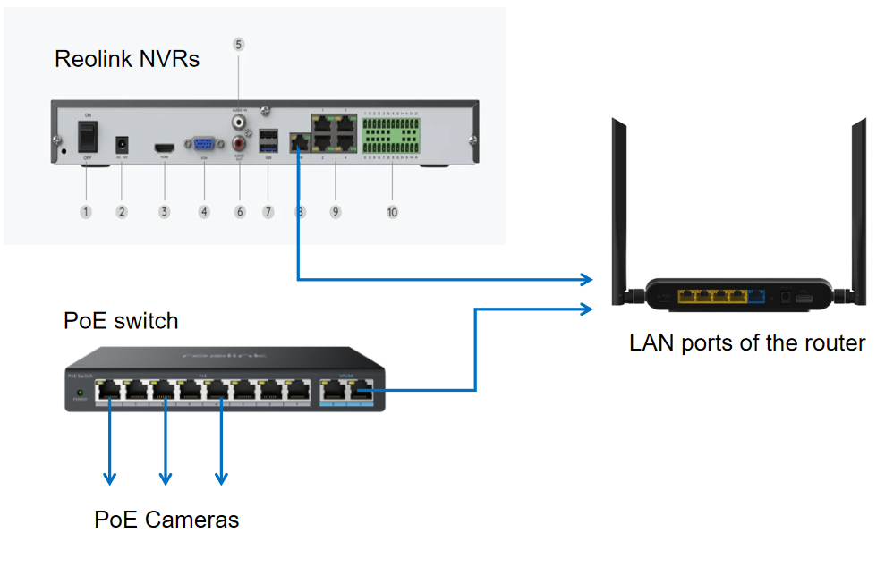
There are two common starting points: plug cameras into the built-in PoE ports of a compatible recorder, or power them through a separate PoE switch and connect the recorder over the network. A single standalone camera can also use a suitable injector. Choose the layout before deciding where every cable should end.
For a matched camera-and-recorder kit in one building, direct connections can be straightforward. A separate switch can be useful when several cameras share a distant part of the property or you want independent access to supported cameras. Neither arrangement automatically makes mixed brands compatible.
| Layout | Where camera cables terminate | Check before buying |
|---|---|---|
| Recorder with integrated PoE | Recorder camera ports | Supported models, channel count, power budget and cable route |
| Separate PoE switch | Switch, with a network path to the recorder | Per-port power, total power, uplink and recorder support |
| Single-camera injector | Injector’s power-and-data output | Required PoE standard and independent recording option |
Separate the camera’s job from its convenient mounting spot
Write one sentence for each view: recognize a visitor at the porch, show activity around the parked car, or document the side-gate approach. Then check the lens and proposed distance against that job. A camera mounted high above the front door may show the entire path while missing faces beneath it.
Try a safe temporary position before drilling. Have a helper walk the ordinary route rather than pose directly in front of the lens. The camera-location guide helps plan coverage, and the placement acceptance checklist turns that plan into a repeatable test.
Make an equipment sheet
Record the exact model and hardware revision for every camera, recorder and power source. Include the required IEEE PoE standard, maximum power requirement, supported video formats and intended storage. Do not use the word PoE as though it guarantees identical power or recording compatibility.
An Ethernet socket is not proof that a camera accepts power through it. Reolink’s powering instructions, for example, distinguish model requirements and reject passive injectors for its PoE cameras. Use the actual device instructions rather than copying the electrical requirements of another product.
Keep the sheet with your receipts. It will later tell an installer or support technician which device, port and cable are associated with the garden view, without dismantling the whole system to identify it.
Check the power budget before counting spare ports
A switch can have enough sockets but insufficient power for all the attached devices. Check both the limit on each port and the shared budget available across the switch. A camera with a motor, illumination or heating may need more power under particular conditions than during a short indoor preview.
Axis explains the distinction between typical and maximum consumption in its camera power guidance. Use maximum requirements and the power source’s allocation rules for capacity planning; a daytime measurement is not a substitute. Include any access point or other device sharing the same power budget.
Leave a documented allowance for additions rather than assuming a nominally unused port guarantees future capacity. Also plan backup power for the recorder and relevant network equipment, not just the cameras. Our backup-power guide covers that separate calculation.
Measure the route, not the straight-line distance
A camera 20 meters from the recorder may need considerably more cable after following an attic route, going around an obstruction and allowing for termination. Measure the intended installed path, including service loops and patch leads. Label both ends before several similar cables arrive at the same cabinet.
Ordinary structured-cabling designs distinguish the fixed permanent link from the complete channel. Fluke Networks describes the usual 90-meter permanent-link and 100-meter channel limits. Those limits do not mean any cable below that length will deliver dependable PoE in every environment.
Do not plan an outbuilding link by stretching an ordinary cable beyond its supported design. Long routes, separate buildings, exposed runs and uncertain electrical bonding call for a properly selected network arrangement and competent installation.
Select cable for the environment as well as the category
Cat5e or Cat6 suitability depends on the intended link, installation and device requirements. The jacket and conductor construction also matter. An indoor patch lead does not acquire outdoor or burial suitability because it has a higher category number.
Buy from an accountable supplier and confirm conductor material. Fluke Networks warns about copper-clad aluminum cabling sold as category-compliant cable. A cheap reel that appears to work on the table can still be the wrong choice for a permanent powered run.
Plan connectors for the actual cable gauge, conductor type and camera gland. Preterminated plugs can simplify a short installation, but oversized boots may not pass through the supplied weather seal. Do not cut away protective fittings to make an unsuitable plug fit.
Bench-test the complete recording path
Before cable pulling, connect one camera with a short known-good lead and the intended power source. Set its owner credentials, identify it by model and confirm that the selected recorder can add it. Test the actual stream and recording mode you plan to use.
Save a short event, play it back and export a file. Then repeat with the remaining cameras, labeling each as you go. This separates a hardware or compatibility problem from a fault introduced by the installed route.
Do not initialize a storage device containing footage you need. For an existing system, export important material first and document current settings. The recording diagnosis guide explains why a live feed alone is not proof that storage works.
Keep physical installation within your competence
Check for concealed services and choose fixings appropriate to the mounting surface. Use safe access equipment and do not lean out of an upstairs window to save the cost of an installer. A heavy camera or junction box needs suitable support, not just screws that happen to fit.
Building penetrations, fire barriers, cable separation and outdoor electrical work have location-specific requirements. Use a qualified installer where those issues arise. PoE reduces the need for a mains outlet beside the camera; it does not make every part of the installation risk-free.
Protect the recorder and switch from moisture, excessive heat and accidental unplugging while maintaining their required ventilation. A closed decorative cabinet can conceal equipment neatly and still be an unsuitable operating environment.
Protect outdoor connectors, not only the camera body
An outdoor camera’s enclosure rating does not automatically protect an exposed network connection. Use the supplied compatible waterproof connector and any required junction box. Follow the sequence in the manual so the seal is on the cable before the connection becomes inaccessible.
Reolink’s junction-box instructions show model-specific mounting and cable-entry parts. The example is useful because it makes those separate seals visible; it is not permission to fit that box to every camera.
Provide strain relief and a route that does not guide water into the connector. Assess surge protection and bonding with the equipment maker and competent installer, especially for exposed or inter-building copper. Tape around a loose coupling is not a complete weather or surge design.
Configure addresses and accounts deliberately
A camera on a recorder’s dedicated PoE ports may be on a different network from the household LAN. A switch-connected camera may obtain its address from the router. Use the manufacturer’s supported setup rather than assuming every device should be assigned a random address in the same range.
Use unique credentials, supported firmware and appropriately restricted sharing. Do not open broad router port ranges merely to make remote viewing work. Follow a supported secure access method and keep a private record of administration and recovery ownership.
With mixed brands, test audio, motion events and playback separately from basic video. The NVR compatibility guide explains why a picture appearing is only the first integration test.
Verify the installation in normal conditions
Repeat the original walk test after the cameras are mounted. Check the beginning of an event, moving detail after dark, timestamps and the saved original. Confirm that lighting does not reflect off a nearby wall or window and wash out the useful scene.
Test the supported restart and recovery sequence with the system owner. Observe whether recording resumes after an ordinary restart and whether authorized remote access returns. Do not conduct disruptive power tests during an incident or while a recorder is updating.
| Requirement | Evidence to keep |
|---|---|
| Useful coverage | Daytime and nighttime walk recordings at the intended distance |
| Power and network | Model list, port map and documented budget |
| Recording | A retrieved original clip and the selected retention policy |
| Safe servicing | Cable labels, equipment access and installer details |
| Ownership | Authorized accounts and recovery arrangements stored privately |
These records turn a working installation into a maintainable one. They also make it possible to tell whether a later problem follows a camera, a cable or a shared device.
Common questions before you finish
Do PoE cameras need internet?
Not necessarily for local recording on a supported system. Remote viewing and online services are separate functions; compare them in our offline-camera guide.
Does plugging into a switch start recording?
No. Power and network access do not select storage or a recording schedule. Configure and test the recorder, camera card or other supported destination.
Can I install everything myself?
A simple supported setup may be manageable, but cable routes, electrical protection and building requirements can justify professional help. Choose the installer based on the work involved, not the apparent simplicity of one Ethernet plug.
For related buying and troubleshooting decisions, return to the camera guide directory. Complete the acceptance tests before treating the installation as dependable security coverage.