How to Connect a PoE Switch to an NVR: LAN Ports, Camera Addresses and Recording Checks
.sl-poe table{border-collapse:collapse;width:100%;margin:22px 0}.sl-poe th,.sl-poe td{border:1px solid #bdcbd0;padding:12px;text-align:left;vertical-align:top}.sl-poe th{background:#edf4f2}.sl-poe .table-scroll{overflow-x:auto}.sl-poe figure{max-width:900px;margin:28px auto}.sl-poe img{max-width:100%;height:auto;display:block;margin:auto}.sl-poe figcaption{font-size:14px;line-height:1.6;color:#425c63;padding-top:9px}
The cameras are powered, the switch lights are flashing and the NVR still shows empty channels. That does not necessarily mean the equipment is incompatible. The camera may be on a different network, the recorder may have the wrong credentials, or the switch may be connected to a port that does not perform the role you assumed.
A common supported layout puts the NVR’s LAN port and the PoE switch on the same local network, then adds the switch-powered cameras to the recorder. Other arrangements exist, especially with dedicated recorder camera ports, but they must be checked against the exact model. This guide focuses on getting the topology, discovery and recording stages right without resetting a working system blindly.
Identify the NVR’s different ports
A recorder can have a LAN connection for the household network and a bank of PoE camera ports serving a separate internal network. The sockets may look identical while behaving differently. Read their labels and the model’s diagram before moving cables.
The LAN port is not necessarily a PoE output. Conversely, a powered camera port should not be treated as an ordinary interchangeable uplink simply because the plug fits. Special switch-to-camera-port arrangements are manufacturer-specific, not the default assumption for a new installation.
| Connection | Typical role | What to verify |
|---|---|---|
| NVR LAN port | Connects the recorder to the local network | Supported topology, link speed and address configuration |
| NVR PoE camera port | Powers and connects a supported camera | Private network behavior and permitted expansion |
| Switch camera port | Powers the camera and carries network data | PoE standard, allocation and port configuration |
| Switch uplink | Connects to the wider network or recorder LAN path | Traffic capacity, isolation rules and correct destination |
Keep the old layout documented when modifying an existing system. A photo of the labeled rear panel can prevent an unnecessary outage when several identical cables are disconnected.
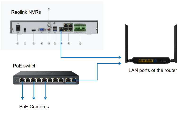
One arrangement connects the NVR and PoE switch to separate LAN ports on the same router. Another connects the recorder to the switch and the switch to the router. When the equipment and configuration support it, both can provide a local path between cameras and recorder.
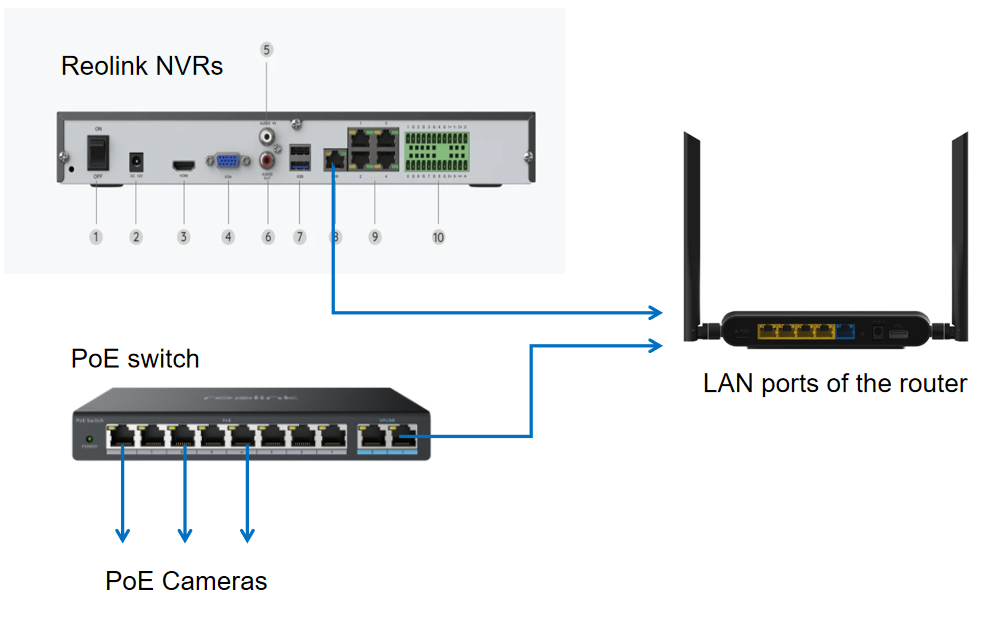
In Reolink’s documented layouts, cameras on the external switch can receive addresses from the router, while cameras connected directly to the NVR use the recorder’s camera network. Independent camera access also differs between these paths. Treat those details as a model-family example rather than a promise that every brand works identically.
Do not connect multiple parallel cables between the same network devices as an improvised speed upgrade. Unplanned loops can disrupt connectivity. Use only a deliberately configured and supported topology.
Check recorder limits before adding cameras
A switch creates network connection points; it does not automatically grant the recorder additional channels or licenses. Check the exact model’s maximum supported cameras, incoming bandwidth, decoding and storage capability. Count existing cameras as well as the new ones.
Swann’s switch-connection guidance explicitly warns that adding a switch does not itself increase supported camera count. Newer or different recorders can have different network-versus-direct-port capacities, so use the manual for your actual unit rather than a universal eight-channel rule.
For mixed brands, check the required stream and protocol support. The ONVIF and RTSP guide separates live video from audio, events and advanced features that may not integrate.
Power the cameras with a suitable source
The external switch must satisfy each camera’s PoE requirement and the group’s total allocation. A free socket is not proof of spare power. Confirm that the chosen ports actually provide PoE; some switches combine powered and unpowered interfaces.
Test the cameras with short known-good cables before using permanent runs. This makes it easier to distinguish a power problem from discovery or credentials. Keep the power supply and cabling appropriate to the switch’s operating environment.
Use the switch-sizing guide for the budget and the injector comparison for a single added device. An existing NVR power arrangement may still be suitable for some cameras while the external switch supplies others.
Confirm addresses without guessing
Use the router’s authorized device list, manufacturer discovery tool or recorder interface to identify the camera. Record the address, model and physical location. Do not identify a device only by an unfamiliar generic hostname.
For a simple supported LAN, DHCP can supply addresses initially. A documented reservation may help keep the chosen address stable where the router supports it. Random static addresses can create conflicts or place the camera outside the expected network.
Never change the router’s entire address range just to match one camera left over from another installation. Follow its supported initialization or network-change process, preserving any needed configuration and authorized access.
Initialize ownership and credentials
A new camera may require activation and an owner password before the recorder can use it. A previously configured camera may retain credentials that differ from the recorder’s login. Adding it to a network does not remove that authentication requirement.
Use unique appropriate credentials and the camera’s supported setup process. The recorder may need a camera account with the specific permissions required for streaming and recording. Do not publish or store the owner password in a visible label on the recorder.
If you cannot establish legitimate ownership or reset authorization, contact the original owner or official support. Do not use generic default-password lists as a substitute for the proper account-transfer process.
Add the camera to the correct channel
Use the recorder’s documented discovery or manual-add workflow. Confirm the intended protocol and any required port values from the camera documentation rather than copying them from a forum about a different model.
Reolink’s new-interface instructions distinguish directly connected cameras from devices discovered over the LAN. The menus are a concrete example, not instructions that apply unchanged to a Swann, Hikvision or other recorder.
Name the channel for the physical scene and keep its previous history in mind when replacing equipment. Deleting and recreating channels can complicate playback or settings on some systems. Export important recordings before a major reconfiguration.
Discovery can fail while the network path works
Automatic discovery may rely on traffic that does not cross every VLAN, isolated port or guest network. A camera can be reachable through an authorized route while not appearing in a discovery list. That does not justify disabling the entire firewall.
Ask the network administrator to check the intended segmentation and permissions. Keep changes narrow and documented. A managed camera network may deliberately prevent general household devices from accessing cameras while allowing the recorder.
Start with a simple approved test topology only when doing so will not compromise an operational system. Record which controlled change allowed discovery; otherwise the eventual fix can become impossible to maintain.
Check recording separately from live video
Once the picture appears, select the intended stream and recording schedule. Confirm that the recorder’s storage is healthy and that the camera is assigned to the required recording policy. Motion markers and continuous video are different kinds of evidence.
Trigger an ordinary event, note the time, wait for it to be saved and play it from the recorder’s actual history. Then export a sample. Viewing footage from a camera’s memory card in the app does not prove the NVR is recording a second copy.
The recording troubleshooting guide covers that distinction, while the export guide explains original-file checks. Avoid formatting storage merely because a playback filter initially shows no result.
Separate internet failure from local recording
A local network can continue connecting cameras and recorder without internet access when the equipment supports that arrangement. Remote viewing, cloud features and online account functions may behave differently. Specify which functions you expect during an outage.
Do not confuse a router losing its internet connection with the router itself losing power. If the local switching path also disappears, recording can be affected for a different reason. Backup power should reflect the actual physical path.
Our offline operation guide and power-backup guide help plan these separately. A successful remote app session is not the only acceptance test.
Diagnose the symptom before changing the layout
| Symptom | Useful first check |
|---|---|
| Camera has no expected power indication | Compatible source, powered port and known-good cable |
| Camera works directly but not via the switch | Address, credentials, topology and port configuration |
| NVR reports authentication failure | Correct authorized camera account and permissions |
| Video works but smart events do not | Exact protocol and feature compatibility |
| One channel is available only intermittently | Duplicate addresses, power behavior and physical link logs |
| Live view works but playback is empty | Recording destination, schedule, storage and time filters |
Preserve error messages and test results. A support request stating that the camera works on a particular short cable but fails on one installed route is more useful than a list of resets performed without observations.
Handover the configuration, not just the picture
Keep a private topology, channel list and record of authorized administration. Label cables at both ends, document where the switch receives power and identify who maintains it. Protect backup copies of the configuration because they may contain sensitive network information.
Verify normal restart behavior through the manufacturer’s approved process and repeat a night recording check. The installation is complete when the intended footage remains retrievable, not when every channel briefly displays a picture during setup.
Frequently asked questions
Should the switch connect to the NVR LAN port or a camera port?
Use the exact recorder’s supported topology. A shared-LAN connection through the LAN path is common; camera-port expansion is not something to assume across brands.
Does a switch increase the NVR’s camera limit?
Not by itself. Check the recorder’s actual channel and bandwidth limits, including any documented distinction between direct and network-connected cameras.
Why can I see the camera in its app but not on the recorder?
The app and recorder may use different network paths, credentials or protocols. Verify those and the recorder’s compatibility rather than assuming the image guarantees integration.
For the full project sequence, use the PoE installation guide. A well-documented connection is easier to extend and considerably easier to repair.