PoE Camera Not Powering On? Check Compatibility, Ports and Cable Before Resetting
.sl-poe table{border-collapse:collapse;width:100%;margin:22px 0}.sl-poe th,.sl-poe td{border:1px solid #bdcbd0;padding:12px;text-align:left;vertical-align:top}.sl-poe th{background:#edf4f2}.sl-poe .table-scroll{overflow-x:auto}.sl-poe figure{max-width:720px;margin:28px auto}.sl-poe img{max-width:100%;height:auto;display:block;margin:auto}.sl-poe figcaption{font-size:14px;line-height:1.6;color:#425c63;padding-top:9px}
A camera that does not appear in the app is not necessarily unpowered. It may have booted with an unexpected address, retained old credentials or joined the recorder’s private camera network. Before replacing a supposedly dead unit, establish whether the fault is electrical power, the Ethernet link or the viewing path.
Start with the exact camera’s power requirement and a short known-good cable on a compatible source. That comparison is usually more informative than a factory reset. This guide follows a controlled sequence so you can identify the failing component without erasing useful configuration or repeatedly changing several things together.
Stop if there is visible electrical damage
Do not keep energizing a wet, burned, damaged or unusually hot connection to see whether it eventually works. Isolate the relevant equipment through its approved procedure and obtain appropriate assistance. Avoid opening a mains-powered switch or injector.
Outdoor connections should be inspected only when access is safe. A fault occurring during rain is not a reason to climb a ladder in poor conditions. Keep any existing recordings needed for an incident before undertaking disruptive maintenance.
Find evidence of power without relying on one light
Read the camera’s documented startup indications and the switch’s PoE status. Some cameras have visible indicators, some do not, and infrared emitters are not always a reliable visible test. A disabled light or a particular wavelength can make a powered camera look inactive.
A network-link light and a PoE-power indication may represent different functions. Check their meanings for the exact switch. Do not look directly into illumination emitters or touch exposed connector pins as an improvised power test.
| Observation | Likely next branch | What it does not prove |
|---|---|---|
| PoE status reports no powered device | Compatibility, cable and physical connection | The camera is definitely irreparable |
| Power is allocated but app cannot connect | Boot status, network address and access | A new injector is necessarily needed |
| Link works but power is denied | Budget, port policy and required class | The cable meets every PoE requirement |
| Camera repeatedly starts and stops | Power under load, cabling and reboot policies | A factory reset will fix the cause |
| Several cameras fail together | Shared switch, supply or network dependency | Every camera has independently failed |
Save the actual status message. An error such as power denied is useful evidence that disappears from the diagnosis when it is summarized only as camera offline.
Confirm the camera really supports PoE
An Ethernet socket can carry data while the camera requires a separate power adapter. Check the model and hardware revision, not a similar product’s description. If the camera is PoE-capable, identify the exact supported standard and power requirement.
Reolink’s power guide separates model requirements and warns against passive injectors for its PoE cameras. Its alternative adapter requirements also differ by product. Do not generalize a 12 V adapter recommendation to every camera or doorbell.
Use only a documented compatible arrangement. A connector fitting physically is not evidence that voltage, polarity or PoE behavior matches.
Check the source and the specific port
A router or ordinary switch may provide data but no PoE. A PoE switch may have powered and unpowered ports, while an NVR’s LAN port can have a different role from its camera ports. Read the labels before assuming any spare Ethernet socket supplies camera power.
For an injector, identify data-in and power-plus-data-out. Plugging the camera into the input will not create the intended powered connection. Follow its diagram and keep its mains supply within the specified environment.
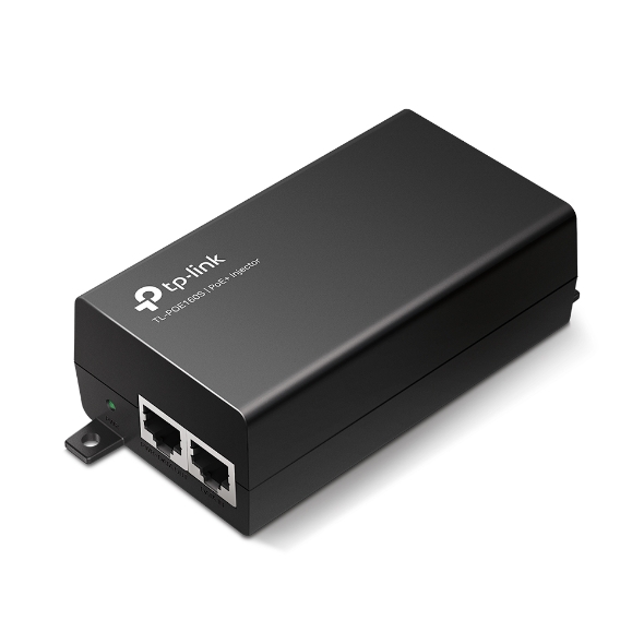
The power-source comparison explains the alternatives. Adding a switch or injector is useful only when it addresses the missing function in your actual setup.
Do not confuse active and passive power
Active standards-based PoE and passive power arrangements are not interchangeable simply because both travel through an Ethernet cable. A camera requiring a higher supported power type may also fail on a source that supplies only a lower one.
TP-Link’s seven-cause troubleshooting guide treats these mismatches separately from cable distance, total budget and administrative settings. Check compatibility before trying another source, and never connect an unidentified passive injector as a test.
If the installation uses proprietary equipment, follow that system’s documented pairing. Stop at uncertainty rather than attempting a voltage or pin modification based on an unrelated online diagram.
Use a short-cable baseline
Bring the camera to a safe test position when practical and connect it using a short known-good Ethernet lead and a confirmed compatible source. Keep the camera’s configuration unchanged initially. Observe the documented startup and network behavior.
If it works there but fails on the installed route, the route, terminations or associated connections deserve attention. If it does not work, the source may still be unsuitable or faulty; the result is not conclusive until the comparison equipment is verified.
Do not change the cable, camera, source and firmware simultaneously. A working result afterward would not identify which change mattered, making a later recurrence harder to resolve.
A useful substitution matrix
| Controlled test | What the result can suggest |
|---|---|
| Original camera, short verified lead, compatible verified source | Whether the camera operates away from the installed route |
| Original camera and short lead, different suitable port | A port-specific configuration or hardware issue |
| Known-good compatible camera on the suspect route | Whether a route fault follows the connection rather than the original camera |
| Original camera on an alternative manufacturer-approved power method | Possible difference between its PoE and other supported power path |
Match the comparison device’s requirements to the test source. A lower-power camera working does not prove the port can supply a more demanding one. Avoid moving suspect damaged equipment onto an operational system without appropriate assessment.
The last camera connected may fail because the switch has reached its overall allocation limit. Some sources prioritize certain ports when power is constrained. Look at the actual budget and policy instead of concluding the newest camera is defective.
Use the maximum or negotiated requirements appropriate to that source. The live measured draw may be smaller than the allocation the switch reserves. Include other devices sharing the same power supply and check any temperature-related limitations in the manual.
The switch sizing guide provides worked budget examples. Do not disable important cameras merely to conceal a permanently undersized source; use controlled tests and correct the design.
Check administrative controls before replacing hardware
A managed switch can have PoE disabled on a port or a schedule that intentionally removes power. A configured limit, port priority or recovery feature may also affect behavior. Document current settings before changing them.
Ask the responsible administrator to review policies on a business or shared network. A change that revives one camera can disrupt isolation, power allocation or other equipment elsewhere. Use the narrowest supported correction.
Do not assume a switch needs a factory reset because one port is off. Resetting can erase useful configuration while leaving the actual cable or source mismatch untouched.
Why a cable can pass a simple test and still be suspect
A basic wire-map test does not establish every characteristic needed for reliable powered operation. Poor terminations, resistance problems or unsuitable conductor material can matter even when a continuity indicator looks normal.
Fluke Networks’ resistance-unbalance guidance discusses installation and cable-quality issues affecting PoE. A competent installer with suitable equipment can provide more meaningful testing than repeatedly reseating the same connector.
Check route length, joins and environmental damage. The cable selection guide explains why switching category alone does not repair an unsuitable jacket, damaged contact or incorrectly matched plug.
Inspect outdoor connections safely
Look for water exposure, corrosion, damaged seals or cable strain at accessible junctions. An outdoor-rated camera can still have a vulnerable network socket if the intended cap was omitted. Do not seal over an already wet or damaged connection and call it repaired.
Use the outdoor connection guide to identify what needs professional or manufacturer-approved correction. Preserve pictures of the condition before parts are replaced.
If the problem started after a storm, consider shared source and surge damage as well as the camera. A port that still passes data can have a different fault from one whose powered output has failed.
Alternative power tests must be explicitly supported
Some cameras accept a documented separate power adapter, while others are PoE-only or require a different input. An approved alternative can help a technician distinguish power paths. It is not permission to try any adapter with a fitting plug.
Check whether simultaneous sources are permitted before connecting them. Follow the manufacturer’s procedure and avoid probing live pins with improvised equipment. A simple safe comparison is preferable to turning a diagnosis into an electrical experiment.
If the camera remains unresponsive on verified compatible arrangements, contact support with the model, serial number privately, source details and controlled results. A targeted warranty assessment may be more useful than more resets.
Inspect network discovery, assigned addresses and credentials through authorized tools. A camera directly connected to NVR camera ports may not appear on the ordinary household network. That is a topology issue rather than proof of absent power.
The NVR connection guide explains those paths. If the camera appears but fails to save video, use the recording guide instead of continuing electrical troubleshooting.
Verify the repair under ordinary use
Check daytime operation, normal night illumination and the saved timeline. Retrieve an original clip and confirm the intended notifications. A single successful boot on the bench does not prove the installed run is reliable.
Keep a record of the actual correction: replaced damaged termination, corrected source standard or removed an unintended power schedule. That makes a future fault easier to distinguish from the one already resolved.
Frequently asked questions
Does no infrared glow mean no power?
Not universally. Indicator behavior, illumination settings and wavelength vary. Use documented device and source status rather than one visual assumption.
Should I reset the camera first?
Usually establish power compatibility and the physical path before a destructive reset. Resetting cannot fix a source that does not supply the required power.
Why does one camera work on the same port and another not?
Their requirements can differ, or one device can be faulty. Check exact models and controlled tests before assuming the working camera proves every capability of the port.
For the original installation requirements, return to the PoE setup guide. The aim is to identify the failing stage, not accumulate replacement boxes until the symptom temporarily disappears.